Retargeting
c: Jan 13, 2022Animation Retargeting
Problem: “You are given a skeletal animation from motion capture data. Your task is to drive any virtual characters that contain a skeletal bone structure. To drive this character, you will want to use the motion capture data.”
In this session, I will only go through rotation.
Solution:
def rotate(Node s, Node t):
Get the bind pose rotation of s.parent and t.parent
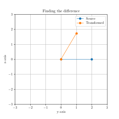
Find the difference between these rotations, r_diff
Estimate the rotation angle, r_a of animated pose for s
Find the required rotation using r_a and r_diff as r_r
Apply r_r to the target node, t
Setup
Our setup is as below
Source Skeleton has two nodes.
Source Node A(root) is of \(2\) units, spans from \((0, 0, 0)\) to \((0, 2, 0)\). The initial bind pose rotation is \(45^\circ\).Source Node B(child) is of \(1\) unit, spans from \((0, 2, 0)\) to \((0, 3, 0)\). In terms of local co-ordinate of B, it spans from \((0, 0, 0)\) to \((0, 1, 0)\). The rotation is \(60^\circ\) in terms of world co-ordinates and \(15^\circ\) in terms of local co-ordinates..png)
.png)
Target Skeleton has two nodes.
Target Node A(root) is of \(2\) units, spans from \((0, 0, 0)\) to \((0, 0, 2)\). The initial bind pose rotation is \(-30^\circ\).Target Node B(child) is of \(1\) unit, spans from \((0, 0, 2)\) to \((0, 0, 3)\). In terms of local co-ordinate of B, it spans from \((0, 0, 0)\) to \((0, 0, 1)\). The rotation is \(-90^\circ\) in terms of world co-ordinates and \(-60^\circ\) in terms of local co-ordinates..png)
.png)
Source node is animated by applying the following local rotations on it’s node.
Animated Node A(root) with \(15^\circ\) rotation.Animated Node B(child) with \(225^\circ\) rotation..png)
Step 1: Find the world bind pose rotation of parent
First we get the bind pose rotation that for the source node’s parent, as well as target node’s parent. In our case these are \(45^\circ\) and \(-30^\circ\) respectively.
Step 2: Calculating the difference between parents’ bind pose
Now we proceed to find the calculate the difference between the parent nodes’ bind pose rotation. \[ \text{diff} = (\text{source bind pose rotation})^{-1} (\text{ target bind pose rotation}) \]
The inverse operation reverses the rotation. In our case that it resets the rotation for Source Node A. This will amount to \(-45^\circ\). Adding the Target Node A rotation, we will get the difference between them which is \(-75^\circ\).
 |
|---|
Step 3: Estimate the rotation angle for the animated pose
It is time to calculate the animated pose rotation offset from the parent bind pose. It always brings the animated pose into the frame of the source pose. Since we want the target to use this source pose, the animated offset will give us the rotation when viewed \(0^\circ\) reference considering bind pose as the true reference.
In our example, the \(225^\circ\) rotation of Animated Node B is actually \(-90^\circ\) rotation from the \(0^\circ\) perspective when we put.
.png) | .png) |
|---|
Step 4: Apply the difference to the animated pose.
We check the product between the source bind pose rotation and animated pose rotation offset. Depending on the cosine value, we will flip the sign of the diff. This is done to prevent self rotation in an axis which results in smoother rotation. \[ \text{dot} = (\text{animated rotation offset} \cdot \text{source bind pose rotation}) \\ \]
\[ \text{animated rotation offset} = \begin{cases} (\text{animated rotation offset})(-\text{diff}) & \text{if,}~ \text{dot} < 0\\ (\text{animated rotation offset})(\text{diff}) & \text{else} \end{cases} \]
This results to animated rotation offset being \(-165^\circ\).
Step 5: Apply the rotation
As for the target bind rotation, we inverse the rotation. This inversion brings the parent to the world reference without rotation. The required inverted rotation is: \(30^\circ\).
Now we add the parent rotation to this animated rotation. \[ \text{target local rotation} = (\text{animated rotation offset}) (\text{target’s parent bind pose})^{-1} \]
Therefore, final local rotation of Target Node B results to \(-135^\circ\).
| .png) |
|---|
Inspiration
- Special thanks to @sketchpunk for making his animation repo available on Github!
- The visuals are generated from a python notebook